Precision Die Casting
Date: 2026-04-30 / Views: 196 / Category: What is Die Casting?
The following is a detailed explanation of the "Die-Cast Mold Structure Diagram":
1. Die-Cast Mold Core Structure
A die-casting mold typically consists of two primary sections: the Fixed Die (Cover Die) and the Ejector Die.
-
Sprue Bushing: This is the first entry point where the molten aluminum enters the mold.
-
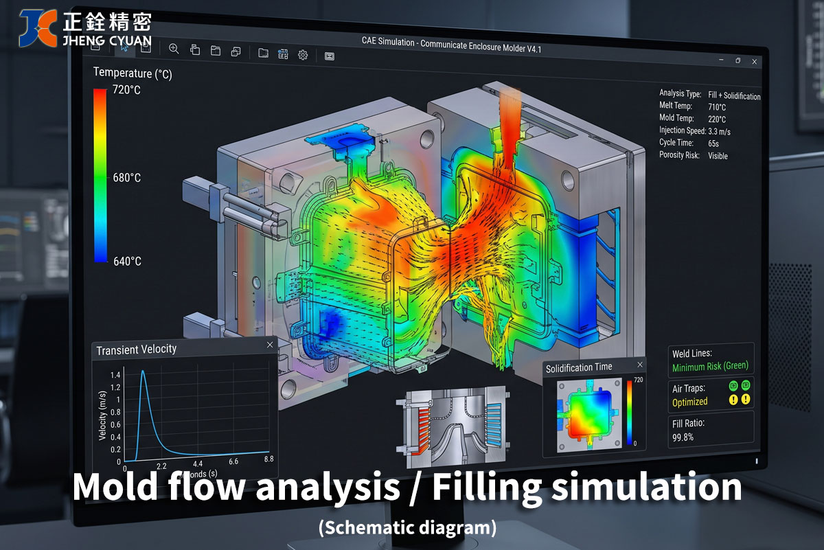
Runner System: Acts like a highway, responsible for guiding the high-pressure molten aluminum into various Cavities.
-
Gate: The most critical narrow opening. The molten aluminum accelerates here, spraying into the cavity at an extremely high velocity.
-
Cavity: The final destination for the molten aluminum, where the fishfinder housing and the "precision grooves" are formed.
2. How Molten Aluminum Enters the "Groove Area"
When designing precision grooves (such as O-ring grooves), the flow of the molten aluminum determines the metal density.
-
High-Speed Filling: As the aluminum enters the groove area, it must maintain high temperature and pressure to prevent a "Cold Shut"—a defect where the aluminum solidifies before completely filling the groove.
-
Vents & Overflows: To ensure the aluminum fills tiny grooves, Overflow Wells are designed at the far end of the groove. This forces the aluminum to "flush through" the groove area, carrying away air and impurities to ensure the groove edges are sharp and solid.
-
Pressure Transmission: At the moment filling ends, the die-casting machine applies a massive "Intensification Pressure" to force the aluminum into every tiny crevice of the mold, eliminating shrinkage porosity.
3. Representation of Precision Grooves in the Mold
In the mold, the grooves are actually formed by "Ribs" on the mold steel.
-
Steel Selection: Since these ribs are very thin and directly endure the wash of high-temperature molten aluminum, molds typically use high-performance hot-work tool steels (such as H13 or DIEVAR).
-
Surface Treatment: These ribs undergo nitriding or PVD coating to reduce friction with the aluminum and prevent "galling" or surface damage to the groove during ejection.
Technical Breakdown Table
|
Component Name
|
Function
|
Impact on Precision Grooves
|
|
Gating System
|
Controls the flow direction and velocity of molten aluminum.
|
Ensures the groove is completely filled and prevents air pockets.
|
|
Overflow Well
|
Collects cold slugs and waste gases.
|
Increases the metal density within the groove area.
|
|
Ejector Pins
|
Pushes the finished part out of the mold.
|
Must avoid groove locations to prevent damaging the sealing surface.
|
|
Cooling Channels
|
Maintains stable mold temperature.
|
Prevents shrinkage cavities caused by overheating in the groove area.
|
 Welcome to consult customized quotation